
Instrument for Thickness Testing PCE-FD 20
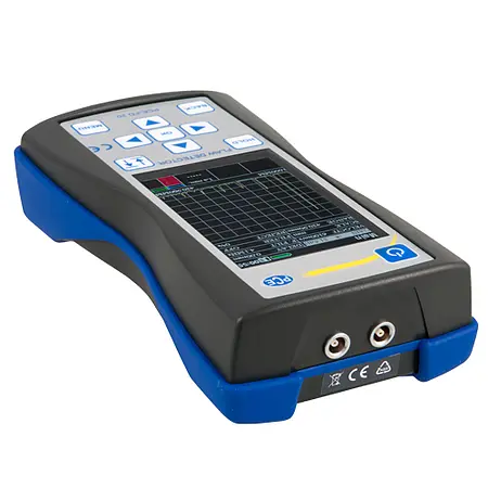
PCE-FD 20 is a portable ultrasonic tester or ultrasonic thickness gauge with a large LCD screen that displays A-scan maps of ultrasonic signals, as well as B-scan cross-sections. Ideal for use in mechanical engineering, aerospace, and metallurgical applications, this high-frequency ultrasound-based thickness gauge uses a contact transducer (two different probes are included; 45° and 90°) to measure material thickness and identify flaws and defects such as joint discontinuity in various welds. It can also store up to 6000 images per gigabyte on the infrared camera’s SD card.
– Measured time interval range: 6 … 1000 microseconds (µs)
– Sound velocity: 1000 … 9999 m/s
– Implements shadow, echo, and mirror-shadow testing methods
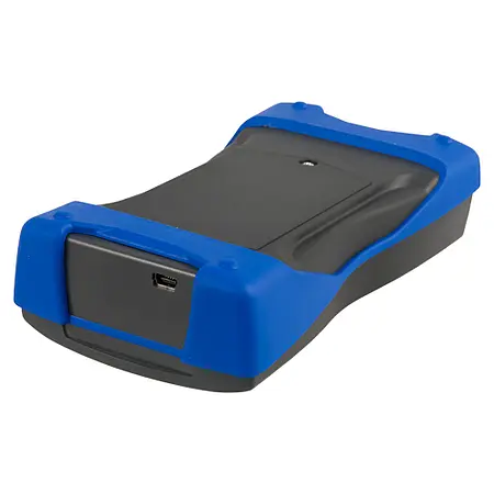
– Features a USB interface for downloading data to PC for detailed analysis
– Lightweight
– Battery or mains power
– 1.5 m probe cable length
Technical Specifications |
|
Operating frequency range |
1 … 10 MHz |
|
Measurement time interval range (scan duration) |
6 … 1000 microseconds (µs) |
|
Sound velocity range |
1000 … 9999 m/s |
|
Time interval measurement deviation |
Does not exceed ± 0.025 µs |
|
Maximum amplitude deviation of signals at receiver input in the range 0 … 110 dB |
Does not exceed ± 0.5 dB |
|
Gain testing range |
125 dB |
|
Averaging over the number of starts |
1 … 16 |
|
Time-variable gain (TVG) range / Number of TVG control points |
40 dB / 15 |
|
Excitation pulse duration to load |
0 … 0.5 µs |
|
Excitation pulse amplitude into 50 Ohm load, not less than |
100, 200, 300 |
|
Receiver operating frequency range at -3 dB |
1 … 10 MHz |
|
Deviation of input signal amplitudes in the range 10 … 100% of screen height |
Not more than 1 dB |
|
Scan |
1 … 1000 µs |
|
Scan delay |
0 … 2000 µs |
|
Time interval measurement range |
0 … 1000 µs |
|
Probe delay prism |
0 … 15 µs |
|
Automatic Fault Signaling (AFS) |
Two gates |
|
Setting the range of AFS gates |
0 … 2000 µs |
|
Adjustment of AFS gate thresholds |
0 … 100% |
|
Signal detection (receiver) |
Positive half-wave, radio mode |
|
Device dimensions (approx.) |
80 x 162 x 35 mm / 3.14 x 6.37 x 1.37″ |
|
Display dimensions (approx.) |
48 x 74 mm / 1.88 x 2.91″ |
|
Power supply |
100 … 250 V AC or 3 AA 1.5 V batteries |
|
Weight (approx.) |
250 g / 0.55 lb (without batteries) |

